
Connectors join two pieces of wiring, allowing for a flexible connection. Understanding Connectors, Wires, and Power Sources Connectors, wires, and power sources must all be correctly connected for an electrical system to work properly. Dashed lines often account for flexible connections such as wires, cables, and connectors.Circles with arrows indicate a transistor, which amplifies a signal as electricity flows through it.The triangle usually represents a diode, which interrupts electricity flow in one direction.The circle signifies a relay, or another switch which uses a magnetic field to open and close the circuit.Common Forms of Electrical Symbols Most diagrams use standard symbols to depict electrical components. Terminals refer to the place where two different wires connect with each other. Likewise, most diagrams also show power sources, such as the car battery or fuse box, as well as wires and connectors. The electrical symbols depict individual components such as resistors, switches, diodes, and relays.

Each of these components works together to transmit electrical current from point A to point B. The Parts of a Palomino Truck Camper Wiring Diagram Palomino truck camper wiring diagrams typically include four distinct parts: electrical symbols, wires and connectors, power sources, and terminals.
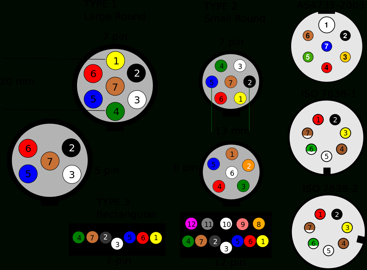
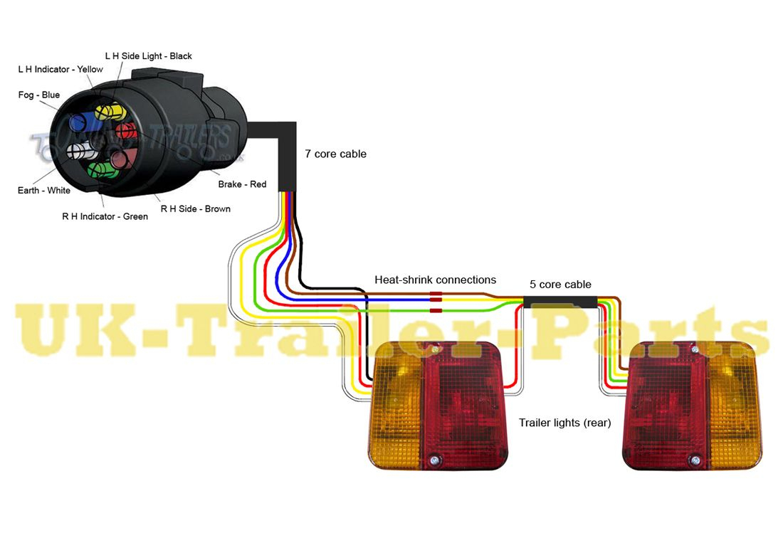
7 PIN TRAILER CONNECTOR WIRING DIAGRAM FOR PALOMINO RV MANUAL
However, never attempt any repairs without referring to the vehicle manual first or having enough mechanical experience to do so. Palomino truck camper wiring diagrams are designed to remain organized and easy to understand. Without a manual or wiring diagram, it can be difficult to correctly diagnose the source of a fault, potentially leading to an ineffective or incomplete repair. It is useful for accurately diagnosing an issue with a vehicle's electrical system and identifying a root cause. Why Use Palomino Truck Camper Wiring Diagrams? A wiring diagram is essentially a map that details how every component is connected to one another. This article explores the design of Palomino truck camper wiring diagrams and provides helpful tips for following them. With a bit of background knowledge, they are an invaluable tool when troubleshooting an electrical problem. Wiring diagrams provide an organization structure of components and their interconnections, as well as designated electrical circuits. The rubber caps just hold the water in.Understanding the Palomino Truck Camper Wiring Diagram for Automotive Maintenance For any automotive venture, understanding the wiring diagram of a Palomino truck camper can help make your repairs and maintenance much easier. All you need is a thin layer of anything (and grease is cheap and sticky) to keep the oxygen (from the air or water) from getting to the copper. It happens when you combine oxygen with copper. Put grease on your trailer plug, (just plain damn grease). (at night, when you step on the brakes, all the trailer lights go out) -see line one, above Trailer Plug Maintenance

If your brake lights work, OR your marker lights work, but everything quits when you turn on both at the same time, your trailer is not grounded to the truck. the "brake light" works on the trailer, the truck just tells then when to flash or not. Still only one light on each side, so if your turn signals work, but not the brakes lights, it is your truck, not the trailer. It's just when they are "on but not flashing", it is assumed to mean brake light. Remember, Trailers DO NOT have "Brake" lights, they have only left and right turn. (add up your load, what could items run at once- example, all lights + brakes) Typically if you have 2 or more brake axles, lots of lights, and use the 12 volt AUX feed to power items, or charge a battery. 30 amps, for those extreme applications, bigger trailers or campers with big loads. 12 Ga, 20 amps, 3 axle brake wire, typical ground wire size, also, 12 volt AUX feed.14 Ga, 15 amps, Lights and up to 2 axle brakes (4 wheels, max).You can not have too many grounds! Make sure your ground wire (typically white) is securely attached to the frame on both the truck and trailer side, preferably at more than one location on the frame! The ground wire should be large enough to handle all the load, do not depend on grounding through the ball. 7 Way Wiring Diagram Other Notes About Trailer Wiring:


 0 kommentar(er)
